Turning of cast iron bearing seats
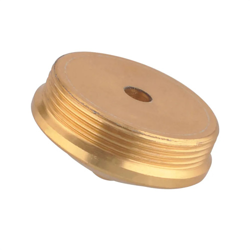
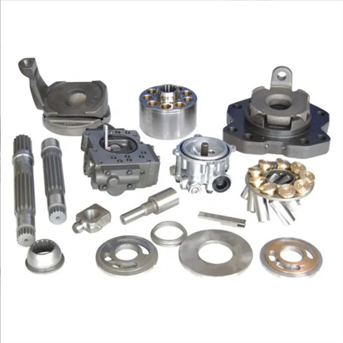
Cast iron bearing seats are key components used to support bearings in mechanical structures. They are widely used in equipment such as machine tools, motors, and reducers. Their structure typically includes a base, bearing hole, and locating stop. High requirements are placed on the bearing hole’s dimensional accuracy, roundness, cylindricity, and perpendicularity to the base. Cast iron bearing seats are typically made of gray cast iron (such as HT200 and HT250), which offers excellent cutting performance and vibration damping properties. However, they are also quite brittle, prone to chip breakage during turning. Therefore, optimal tool selection, clamping method, and cutting parameters are crucial to ensure both machining quality and efficiency.
Clamping cast iron bearing seats is a crucial step in turning, and the clamping method should be tailored to the bearing seat’s structural characteristics. For small and medium-sized bearing seats, a three-jaw chuck with a faceplate can be used. Position the bearing seat’s base against the faceplate surface, secure it with a pressure plate and bolts, and adjust the pressure plate’s position using the faceplate’s T-slots to ensure evenly distributed clamping force and prevent workpiece deformation. Before clamping, clean the mating surfaces between the faceplate and the workpiece to remove burrs and debris. If necessary, place a thin copper sheet between the mating surfaces to ensure accurate positioning. For large or complex bearing seats, a specialized fixture should be used. This fixture features locating pins and support surfaces that align with the bearing seat base. This allows for quick workpiece positioning and clamping, improving clamping efficiency and stability. After clamping, check the bearing seat’s radial and axial runout with a dial indicator to ensure alignment between the bearing bore axis and the lathe spindle axis. Runout should be kept within 0.03 mm, otherwise machining accuracy will be compromised.
Tool selection for turning cast iron bearing seats requires consideration of the material properties of cast iron, with carbide tools being the primary choice. For rough turning of bearing bores, YG8 carbide boring tools are recommended. These tools offer high strength and wear resistance, and can withstand high cutting forces. A rake angle of 0° to 5° and a clearance angle of 5° to 8° are recommended to minimize chipping. For fine turning, YG6 carbide boring tools are recommended, with rake angles of 5° to 10° and clearance angles of 8° to 12°. The cutting edge should be sharp and, if necessary, ground to ensure a surface roughness of the bearing bore (typically Ra 1.6 to 3.2 μm). For turning the base surface and locating stop, carbide facing tools can be used with a 90° lead angle to reduce radial cutting forces and prevent workpiece vibration. The tool shank should be sufficiently rigid, especially the boring bar. The diameter should be selected based on the bearing bore size, generally 0.6 to 0.8 times the bore diameter, to prevent chatter during turning.
The turning sequence for cast iron bearing seats should follow the principles of “facing first, then boring” and “roughing first, then finishing” to ensure machining accuracy. First, turn the base flat surface, using it as a positioning reference for subsequent machining. During rough turning, remove surface defects and excess stock from the casting. Use a feed rate of 0.3-0.5 mm/rev, with a back-cut of 2-3 mm. During finish turning, reduce the feed rate to 0.1-0.2 mm/rev, with a back-cut of 0.5-1 mm, ensuring a flatness error of no more than 0.05 mm per 100 mm. Next, turn the positioning stop. The stop’s diameter and depth must strictly conform to the drawing to ensure proper assembly of the bearing seat with other components. A stop cutter can be used during turning, with dimensional accuracy controlled by a dial. Then, rough bore the bearing hole to remove most of the machining allowance. During boring, maintain a steady feed rate to avoid sudden changes in cutting force that could increase roundness error in the hole. Finally, the bearing hole is precision bored. During precision boring, the hole diameter needs to be measured multiple times, and the final size is controlled by fine-tuning the tool holder to ensure that the diameter tolerance of the bearing hole is within the range of H7~H8, and the roundness and cylindricity errors do not exceed 0.01 mm.
Properly setting cutting parameters is crucial to the turning quality of cast iron bearing seats. The spindle speed is determined by the machining area and tool material. For rough turning of the base surface and bearing bore, the speed is 300-500 rpm; for finish turning, the speed is increased to 600-800 rpm to improve surface quality. The feed rate and back-cut depth are adjusted according to the machining stage. For roughing, higher feed rates and back-cut depths are used to improve efficiency; for finish machining, lower parameters are used to ensure accuracy. During the turning process, cooling is the primary lubrication method. Emulsions or kerosene can be used, especially when fine boring bearing bores. Adequate cooling can reduce tool wear and prevent burns on the workpiece surface. Chips must also be cleaned promptly to prevent broken chips from scratching the machined surface or jamming the tool, affecting machining quality.
Common quality issues and solutions during the turning process of cast iron bearing seats are as follows: Out-of-tolerance roundness of the bearing hole is often caused by insufficient boring tool rigidity, loose workpiece clamping, or low spindle rotation accuracy. This can be resolved by replacing a boring bar with improved rigidity, re-clamping the workpiece, or adjusting the spindle-bearing clearance. Excessive perpendicularity error between the bearing hole and the base plane is usually caused by an uneven positioning reference surface or tilting of the workpiece during clamping. The positioning reference surface needs to be trimmed or a dial indicator needs to be used for alignment during clamping. Unsatisfactory surface roughness may be caused by tool edge wear, excessive feed rate, or insufficient cooling. The tool should be promptly sharpened or replaced, the feed rate reduced, and cooling increased. After machining is completed, the bearing seat needs to be fully inspected. The bearing hole diameter should be measured with an inside micrometer, the flatness and perpendicularity checked with a dial indicator and a plate, and the surface quality checked with a surface roughness tester to ensure that all parameters meet the drawing requirements. Through reasonable clamping, tool selection, and process control, the turning quality of the cast iron bearing seat can be guaranteed to meet the assembly and use requirements of the equipment.