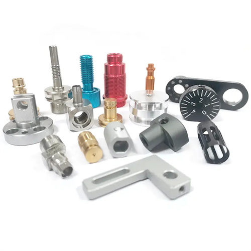
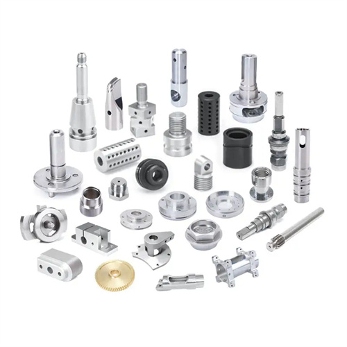
Conical surface turning method
Conical surfaces are common geometric surfaces found in mechanical parts. They offer tight fit and easy disassembly, making them widely used in applications such as tool tapers, machine tool spindle tapers, and pipe connections. Turning conical surfaces is a crucial process in lathe machining, crucial for ensuring the taper accuracy, surface roughness, and dimensional precision of the cone. Depending on the size of the conical surface, the required precision, and the workpiece shape, various turning methods can be employed, such as small carriage indexing, tailstock offset, and profiling. Each method has its own specific application scope and key operational requirements.
The slide indexing method is the most commonly used method for turning conical surfaces. It is suitable for turning short, tapered surfaces, such as taper pins and points. This method works by rotating the slide (upper slide) around the axis of the turntable by a certain angle, aligning the tool feed direction with the generatrix of the conical surface, thereby producing the desired conical surface. To operate, the slide’s rotation angle is calculated based on the taper of the cone. The cone half-angle (α/2) is calculated as tan (α/2) = (D – d)/(2L) (D is the large end diameter, d is the small end diameter, and L is the cone length). The slide’s turntable’s retaining nut is then loosened, the turntable is rotated to the calculated angle, and the nut is tightened. During turning, feed is achieved by manually turning the slide’s handle. Due to the limited travel of the slide (generally no more than 150 mm), this method is only suitable for machining short conical surfaces. The small slide indexing method is simple to operate and easy to adjust, but the feed rate is uneven and the surface roughness is large. It is suitable for rough processing and occasions with low precision requirements.
The tailstock offset method is suitable for turning long, slightly tapered conical surfaces, such as spindle bores and long tapered shafts. The principle is to offset the tailstock’s upper slide outward or inward relative to the base by a certain distance, so that the workpiece’s rotational axis forms an angle (the taper half-angle) with the lathe spindle axis. The turning tool then feeds parallel to the spindle axis, thereby turning the conical surface. The tailstock offset (S) is calculated as S = (D – d) L / (2L0) (L0 is the total length of the workpiece). To perform the offset, loosen the tailstock’s fixing bolts and adjust the tailstock’s adjustment screw to the calculated offset value. A dial indicator is used to check the offset for accuracy. The advantages of the tailstock offset method are that it utilizes the lathe’s automatic feed system, resulting in uniform feed and minimal surface roughness, making it suitable for batch processing. However, the disadvantages are that it can only turn external conical surfaces, and the taper must be limited (typically, the taper half-angle is less than 8°), otherwise, poor contact between the tool tip and the center hole will occur, affecting machining accuracy.
The profiling method is suitable for turning conical surfaces with high turning precision requirements and large batches, and is especially suitable for the processing of long conical surfaces and formed conical surfaces. This method requires the installation of a special profiling device on the lathe. The profiling is equipped with an adjustable profiling plate. The inclination angle of the profiling plate is equal to the semi-angle of the cone. The tool holder contacts the profiling plate through a slider. When the large slide automatically feeds, the slider slides along the profiling plate, driving the turning tool to feed along the generatrix direction of the conical surface, thereby turning a precise conical surface. The adjustment steps of the profiling method are as follows: first, adjust the angle of the profiling plate according to the semi-angle of the cone, and calibrate it with an angle ruler or dial indicator; then adjust the turning tool to the correct position so that the tool tip is at the same height as the axis of the workpiece; finally, lock the profiling device and start the lathe for turning. The advantages of the profiling method are high processing accuracy (taper error can be controlled within 0.01 mm/100 mm), low surface roughness (up to Ra1.6μm), automatic feeding, and high production efficiency; the disadvantage is that it requires a special profiling device, which is suitable for batch production and is not very economical for single-piece small-batch processing.
For conical surfaces requiring extremely high precision (such as gauges and precision machine tool spindle tapers), after rough turning and semi-finishing using the above methods, finish turning and grinding are required. For finish turning, a high-speed steel turning tool should be used. The rake and relief angles should be appropriately increased (rake angle 10°-15°, relief angle 8°-12°) to enhance tool sharpness. Cutting speeds should be maintained at 80-120 m/min and feed rates at 0.05-0.1 mm/rev. Emulsion should be used for sufficient cooling to reduce cutting temperatures and minimize tool wear. After finish turning, if the conical surface still does not meet the required accuracy, grinding is required. This process uses abrasive paste (such as chromium oxide or silicon carbide) and a lap (such as a cast iron conical lap). The lap is coated with abrasive paste and rotated in conjunction with the conical surface. This grinding removes minor surface errors, achieving an accuracy of IT5-IT6 and a surface roughness of Ra 0.8μm or less. During the grinding process, it is necessary to apply pressure evenly to avoid relative sliding between the grinding tool and the workpiece to prevent scratches on the surface.
When turning conical surfaces, common quality problems and solutions are as follows: Inaccurate taper is mainly caused by incorrect calculation of the small slide indexing angle or tailstock offset, or improper adjustment of the template angle. The solution is to recalculate and adjust the angle or offset, and calibrate it through trial cutting. Conical surface straightness deviations are mostly caused by insufficient turning tool rigidity, excessive feed rate, or poor workpiece rigidity. These can be solved by replacing a tool with better rigidity, reducing the feed rate, or adding auxiliary supports. Unsatisfactory surface roughness is usually caused by tool wear, too low a cutting speed, or insufficient cooling. Sharp tools need to be replaced, cutting speeds increased, or cooling and lubrication enhanced. In addition, during the turning process, attention should be paid to measuring the dimensions of the conical surface. Commonly used measuring tools include conical gauges, micrometers, and universal angle rulers. The contact area of the conical gauge is checked by coloring, and the contact area should be greater than 80% to ensure the accuracy of the taper. By selecting the appropriate turning method, fine-tuning, and standardized operations, conical surfaces that meet precision requirements can be turned to meet the assembly and use requirements of mechanical parts.