Cutting parameters for fine turning thin-walled workpieces
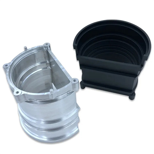
When finishing thin-walled workpieces, the proper selection of cutting parameters is directly related to machining quality and efficiency. The core of this is to balance the relationship between cutting force, cutting temperature, and workpiece rigidity. Thin-walled workpieces are characterized by poor rigidity and are prone to deformation under cutting force. Therefore, the primary principle for determining cutting parameters is to reduce cutting force. Normally, a smaller back-cut should be used, generally controlled between 0.1 and 0.3 mm. This is because excessive back-cutting can lead to a sharp increase in radial cutting force, causing the workpiece to bend or vibrate in the clamping area, thereby affecting dimensional accuracy and surface roughness. For example, when machining a 2mm thick aluminum alloy thin-walled cylinder, if the back-cutting exceeds 0.5 mm, the roundness error of the workpiece’s outer circle may exceed 0.03 mm, far exceeding the requirements of precision machining.
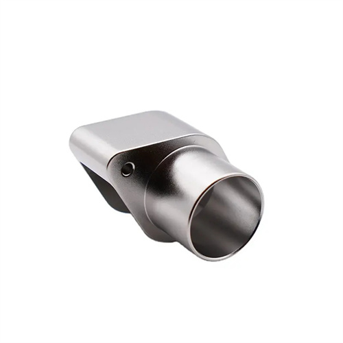
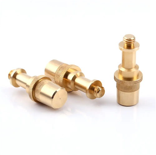
The selection of feed rate needs to take into account both surface quality and production efficiency. A smaller feed rate should be used in the fine turning stage, generally 0.05-0.15mm/r. A smaller feed rate can reduce the contact area between the tool and the workpiece, reduce the heat generated by friction, and make the cutting marks finer, which helps to improve the surface finish. However, a feed rate that is too small will extend the processing time and reduce production efficiency, so it needs to be adjusted according to the characteristics of the workpiece material. For plastic materials such as copper alloys, the feed rate can be appropriately increased to 0.12-0.15mm/r, using the ductility of the material to reduce the generation of cutting edges; while for brittle materials such as gray cast iron, it needs to be controlled at 0.05-0.1mm/r to avoid workpiece cracking due to fluctuations in cutting forces. When a precision instrument factory was processing thin-walled stainless steel parts, by reducing the feed rate from 0.2mm/r to 0.1mm/r, the surface roughness was improved from Ra3.2μm to Ra1.6μm, with significant results.
The determination of cutting speed requires comprehensive consideration of the tool material, workpiece material, and heat dissipation conditions. High-speed cutting can shorten the contact time between the tool and the workpiece, reduce heat transfer to the workpiece, and thus reduce the risk of thermal deformation. Therefore, higher cutting speeds are usually used for fine turning of thin-walled workpieces. For machining steel parts with carbide tools, the cutting speed can be set to 100-150m/min; when machining light metals such as aluminum alloys, it can even be increased to 200-300m/min. However, it should be noted that excessively high cutting speeds will increase tool wear, especially when machining high-strength alloys, which requires sufficient cooling of the cutting fluid to balance it. For example, when machining thin-walled titanium alloy components, an aviation manufacturing company used a cutting speed of 200m/min in combination with an extreme pressure emulsion, which not only controlled workpiece deformation but also extended tool life by 30%.
The selection and use of cutting fluids significantly impacts the effectiveness of cutting parameters. When finishing thin-walled workpieces, cutting fluids must possess excellent cooling and lubricating properties to reduce temperatures in the cutting zone and minimize tool wear. Emulsions are suitable for general steel and aluminum alloy machining, offering superior cooling performance over cutting oils and effectively inhibiting thermal deformation of the workpiece. Extreme-pressure cutting fluids are particularly effective for high-strength alloys, as their sulfur, phosphorus, and other extreme-pressure additives form a lubricating film at high temperatures, reducing adhesion between the tool and the workpiece. Furthermore, the cutting fluid spray pattern must be rationally designed, employing a high-pressure spray directed at the cutting area to ensure adequate cooling. An automotive parts manufacturer, while machining thin-walled bearing sleeves, reduced the workpiece’s cylindricity error from 0.02mm to 0.01mm by optimizing the cutting fluid spray angle, providing reliable support for subsequent assembly.
Dynamic adjustment of cutting parameters is key to processing complex thin-walled workpieces. In actual production, factors such as the workpiece’s structural shape and clamping method can affect the stability of the cutting process, necessitating real-time optimization of cutting parameters based on the machining status. For example, when machining thin-walled parts with steps, the area near the step has relatively good rigidity, so the feed rate can be appropriately increased. In areas with less rigidity, such as the workpiece ends, the cutting speed needs to be reduced to minimize vibration. At the same time, an online monitoring system can collect cutting force, vibration, and other signals in real time, automatically adjusting the cutting parameters when anomalies are detected. After a precision machinery plant introduced an intelligent cutting system, the qualified rate of thin-walled workpieces increased from 85% to 98%, fully demonstrating the importance of dynamic adjustment. In short, selecting cutting parameters for fine turning thin-walled workpieces is a systematic project that requires combining theoretical knowledge with practical experience to achieve a win-win situation in terms of quality and efficiency.