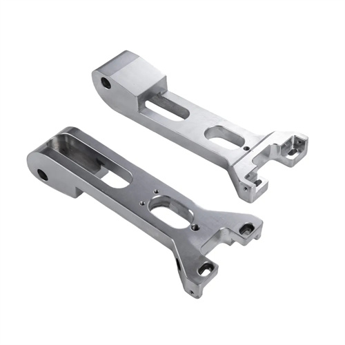
Flat thread turning
A flat thread is a spiral groove machined into the end face of a cylinder or disc. Its profile is typically triangular, rectangular, or trapezoidal. It is widely used in machine tool feed mechanisms, indexing plates, presses, and other equipment for transmission, positioning, or clamping. Compared to cylindrical threads, flat threads are more challenging to turn because the helix unfolds on a flat surface, requiring the lathe to possess precise longitudinal and transverse linkage control capabilities. When turning flat threads, the workpiece is typically clamped to the lathe’s faceplate or chuck and rotates about the spindle axis, while the turning tool is fed radially at a constant speed. By maintaining a strict ratio between spindle rotation and tool feed, a desired spiral trajectory is formed. When machining flat threads on indexing plates, a machine tool manufacturer precisely adjusts the lathe’s transmission ratio to keep the thread lead error within 0.01mm, ensuring indexing accuracy.
The choice of turning tools for flat threads should be determined based on the thread profile and workpiece material. High-speed steel or carbide triangular thread turning tools are commonly used for machining triangular flat threads. The tool tip angle must match the thread profile angle, such as 60° for standard triangular threads and 55° for imperial threads. When machining rectangular or trapezoidal flat threads, corresponding forming turning tools are required, and the tool’s cutting edge width and angle must match the dimensions of the thread groove. For harder materials, such as 45 steel quenched and tempered parts, carbide tools should be selected to improve wear resistance and cutting efficiency. For non-ferrous metals such as copper and aluminum, high-speed steel tools can meet the requirements and achieve better surface quality. An instrument factory uses high-speed steel tools, combined with kerosene cooling, to machine brass flat threads, achieving a thread surface roughness of Ra0.8μm, thus preventing tool sticking.
The process parameters for turning flat threads directly impact machining quality and efficiency. The choice of cutting speed depends on the workpiece material and tool performance. When machining steel, carbide tools can be set to 80-120 m/min, while high-speed steel tools can be set to 20-50 m/min. When machining non-ferrous metals, the cutting speed can be increased appropriately, reaching 60-100 m/min with high-speed steel tools. The feed rate is equal to the lead of the flat thread and is determined based on the thread’s intended use. The lead of flat threads for general transmission applications is generally 1-10 mm, while the lead for flat threads used for precision positioning can be as low as 0.5 mm or less. The back-cut should be cut in layers, with the first pass starting at 0.5-1 mm and gradually decreasing with each subsequent pass, leaving a final finishing allowance of 0.1-0.2 mm to ensure thread dimensional accuracy. A heavy machinery plant achieved a 30% improvement in machining efficiency while machining flat threads for large presses by optimizing back-cut distribution, while also effectively ensuring thread profile accuracy.
The key to flat thread turning lies in ensuring the accuracy of the helix. Because the helix of a flat thread is formed by the linkage between spindle rotation and the radial feed of the tool, the lathe’s transmission system must have a precise proportional relationship. Traditional lathes require adjusting the transmission ratio by replacing the gears. For flat threads with larger leads, a suitable gear combination must be calculated and configured. CNC lathes, on the other hand, can directly set the ratio of spindle speed to feed rate through a program to achieve precise helix processing. During the turning process, sudden changes in tool feed must be avoided to prevent twisting or jumping of the helix. An automotive mold factory uses a CNC lathe to process large flat threads. By writing a macro program to control the radial feed of the tool, the cumulative error of the helix is kept within 0.02mm/m, meeting the mold positioning requirements.
The quality inspection of flat thread turning requires careful attention to several parameters. First, lead accuracy, which can be measured using a lead gauge or universal tool microscope, ensures that the deviation between the actual lead and the designed value is within the allowable range. Second, thread profile accuracy: The thread angle and half-angle are checked using a template or projector to avoid thread profile skew caused by incorrect tool installation angles. Finally, surface quality: The thread surface must be inspected for defects such as burrs, scratches, and built-up edge, and polished or polished as necessary. For precision flat threads, cumulative pitch error must also be checked, which can be achieved with high-precision laser interferometry. An aerospace company employs a “three-inspection system” for flat thread inspection, combining self-inspection, mutual inspection, and specialized inspection, ensuring a consistent product qualification rate above 99.5%. With the advancement of CNC technology, flat thread turning is moving towards higher precision and efficiency, providing strong support for improving the performance of precision machinery.