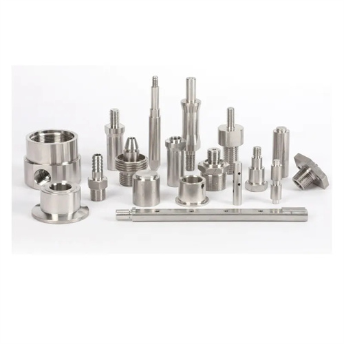
Turning of high temperature alloy stepped slender shaft
High-temperature alloy stepped slender shafts are shaft components designed to operate in high-temperature environments (above 600°C) and feature multiple steps of varying diameters with an aspect ratio exceeding 20. They are widely used in hot-end components such as aircraft engines and gas turbines. Materials primarily include nickel-based superalloys (such as GH4169) and cobalt-based superalloys (such as GH5188). Turning these components presents multiple challenges: Superalloys inherently possess high strength (σb ≥ 900 MPa at room temperature), high hardness (HB250-350), high toughness, and severe work hardening (hardening rates of 200%-300%). The stepped structure leads to uneven rigidity distribution, which can easily cause vibration. Furthermore, the high aspect ratio of the slender shafts makes them susceptible to bending and deformation during machining. Therefore, turning high-temperature alloy stepped slender shafts requires specialized tooling, advanced clamping methods, and optimized process parameters. A systematic approach is required to ensure dimensional accuracy, geometric tolerances, and surface quality.
Specialized tool material and geometry design are fundamental to turning slender, stepped shafts made of high-temperature alloys. Due to the high-temperature strength and wear resistance of high-temperature alloys, ordinary tool materials are insufficient, necessitating the use of high-performance tools. For rough turning, ultrafine-grained carbides (such as WC-Co-TaC , with a grain size of 0.5-1μm ) are used, offering a bending strength of ≥ 1800MPa and the ability to withstand high cutting forces. For finish turning, cubic boron nitride ( CBN ) or ceramic tools are required. CBN tools boast a hardness of HV3000 or higher and wear resistance 5-10 times that of carbide, making them suitable for machining nickel-based superalloys such as GH4169 . For cobalt-based superalloys, Al₂O₃-TiC composite ceramic tools can be used, offering high-temperature resistance exceeding 1200 °C. The tool geometry should be designed to reduce cutting force and work hardening. The rake angle should be -5°-0° to enhance blade strength ; the back angle should be 8°-12° to reduce back face friction; the main rake angle should be 75°-90° to reduce radial cutting force; the inclination angle should be -3°–5° to control chip flow and avoid scratching the machined surface; the tool tip arc radius should be 0.2-0.5mm. A small arc radius can reduce cutting force and work hardening range.
Innovation in clamping methods is key to controlling deformation in slender, stepped shafts made of high-temperature alloys. Traditional three-jaw chucks can cause workpiece deformation due to clamping. This requires a combined clamping method consisting of a live center on one end, a collet on the other, and a steady rest. The live center prevents axial movement of the workpiece, while the collet utilizes spring force to provide uniform clamping, with a clamping force controlled at 5-10 MPa to prevent workpiece deformation. The steady rest utilizes a double-support structure, with support blocks made of polytetrafluoroethylene or carbide. The contact pressure with the workpiece is fine-tuned hydraulically (2-3 N) to ensure uniform contact with the workpiece’s outer diameter and enhance rigidity. For clamping at stepped surfaces, a process boss is installed in front of each step to serve as a temporary support point for the steady rest. The boss is removed after the step is machined. Before clamping, the workpiece must undergo stress relief annealing (900°C for one hour for GH4169) to eliminate internal stresses induced by forging or heat treatment and minimize machining deformation. In addition, the positioning reference of the workpiece should be the center holes at both ends, and the center holes need to be ground (precision IT5 level) to ensure a good fit with the center.
Optimizing cutting parameters must balance machining efficiency and part quality to avoid work hardening and tool overheating. The cutting speed for slender, stepped high-temperature alloy shafts should be strictly controlled: 20-40 m/min for carbide tools during rough turning, and 50-80 m/min for CBN tools during finish turning. Too low a speed can lead to increased work hardening, while too high a speed can cause rapid tool wear. The feed rate is generally 0.05-0.15 mm/r, with higher values (0.1-0.15 mm/r) used for rough turning and lower values (0.05-0.08 mm/r) for finish turning. A lower feed rate can reduce surface roughness, but excessively low feed rates, which can increase friction, should be avoided. The depth of cut should decrease according to the step diameter: 1-1.5 mm for the first layer during rough turning, 0.5-1 mm for each subsequent layer, and 0.1-0.3 mm for finish turning. Ensure the tool edge fully penetrates the workpiece with each cut to avoid extrusion and work hardening at the root of the step. For example, when turning a GH4169 stepped slender shaft (maximum diameter 50mm, aspect ratio 30), the rough turning parameters are: v=30m/min, f=0.12mm/r, ap=1mm; the fine turning parameters are: v=60m/min, f=0.06mm/r, ap=0.2mm, which can effectively control machining deformation and surface quality.

Strengthening the cooling and lubrication system is a key measure to reduce tool wear and machining defects. When turning high-temperature alloys, cutting temperatures can reach over 1000°C, necessitating a high-pressure oil mist cooling and lubrication system. Compressed air pressure is 0.5-0.8 MPa, cutting oil flow is 10-15 L/h, and the oil mist particle diameter is 5-10 μm. This ensures uniform coverage of the cutting area, providing both cooling and lubrication. Cutting oils should be synthetic cutting oils containing extreme pressure additives (such as sulfided isobutylene) with a viscosity of 20-30 cSt at 40°C. These oils form a tough lubricating film at high temperatures, reducing adhesion between the tool and the chips. For difficult-to-cool areas, such as step roots, specialized nozzles can be used for targeted cooling, ensuring that the cutting fluid is sprayed directly onto the contact point between the cutting edge and the workpiece. Furthermore, the cutting fluid must be finely filtered (accuracy ≤ 5 μm) to prevent impurities from scratching the workpiece surface and exacerbating tool wear.
Process planning and precision control must adhere to the principle of refinement to ensure the quality of stepped slender shafts. The machining process should follow a “rough turning – stress relief – semi-finish turning – aging – finish turning” approach: Rough turning removes most of the stock (leaving a 2-3mm stock), using high feed rates for rapid cutting. After rough turning, stress relief treatment (for GH4169, 8 hours at 720°C) is performed to eliminate machining stresses. Semi-finish turning is performed to leave a 0.5-1mm stock on each step to correct for shape errors. After semi-finish turning, aging treatment (such as γ’ phase precipitation strengthening for GH4169) is performed. Finally, finish turning is performed to the designed dimensions, ensuring each step diameter tolerance is IT6-IT7 and perpendicularity between the step end face and the axis is ≤0.02mm/100mm. Multiple measurements are required during the machining process, including diameter measurement using a digital micrometer, straightness checking using a dial indicator (tolerance ≤0.05mm/m), and step positional accuracy using a coordinate measuring machine. For critical steps, an online measurement system can be used to monitor dimensions in real time to ensure machining accuracy. This comprehensive approach enables high-precision and high-efficiency turning of slender shafts made of high-temperature alloy steps, meeting the stringent requirements of high-end fields such as aerospace.