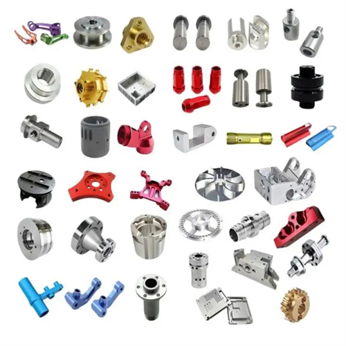
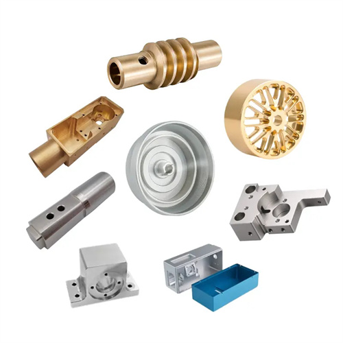
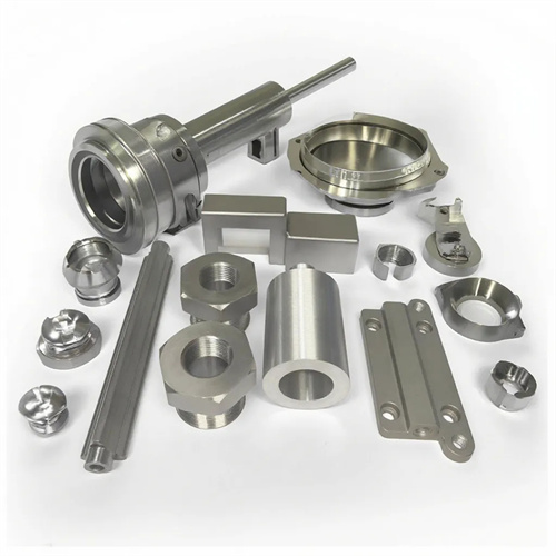
Deformed copper alloy nozzles are widely used in fluid control components in aerospace, chemical equipment, and other fields. They possess excellent thermal conductivity, electrical conductivity, and corrosion resistance, as well as good plastic deformation capabilities. These nozzles are typically complex in structure, often featuring thin-walled, conical or irregular shapes with wall thicknesses of only 1-3mm. The inner bore surface roughness must be below Ra0.8μm, and the axis straightness error must be controlled within 0.02mm/m. Due to the low hardness (HB60-100) and high plasticity of deformed copper alloys (such as brass H62 and bronze QSn6.5-0.1), they are prone to tool sticking during turning, forming built-up edge and causing scratches on the machined surface. Therefore, specialized machining processes are required.
Optimizing tool materials and geometric parameters is key to ensuring the machining quality of deformed copper alloy nozzles. Given the low hardness and high plasticity of copper alloys, sharp and wear-resistant tool materials should be selected. High-speed steel tools (such as W18Cr4V) are suitable for low-speed fine turning, achieving higher surface quality, while carbide tools (such as YG6X) are suitable for high-speed rough turning, improving machining efficiency. The tool rake angle should be 15°-20°; a larger rake angle reduces cutting deformation and lowers cutting forces. The back angle should be 8°-12° to reduce friction between the tool flank and the workpiece. The rake angle should be 5°-10° to direct chips toward the surface to be machined, avoiding scratches on the machined surface. The tool tip radius should be selected based on the nozzle wall thickness; for thin-walled parts, it should be 0.2-0.5mm to prevent excessive cutting forces from causing workpiece deformation.
Proper setting of cutting parameters requires a balance between machining efficiency and surface quality. During rough turning, a higher cutting speed (150-200 m/min), a moderate feed rate (0.15-0.25 mm/r), and a depth of cut (1-2 mm) can be used to quickly remove the stock material. For example, when machining the outer diameter of a 50 mm diameter brass nozzle, a spindle speed of approximately 1000 r/min and a feed rate of 0.2 mm/r are used, with a 1.5 mm thick layer of metal removed each time. Combined with emulsion cooling, this effectively suppresses built-up edge. For finish turning, the cutting speed should be increased to 200-300 m/min, the feed rate reduced to 0.05-0.1 mm/r, and the depth of cut 0.1-0.3 mm. Extreme pressure emulsion (containing sulfur and phosphorus additives) should be used to enhance lubrication and reduce tool-chip adhesion. For thin-walled areas, radial feed should be used to avoid workpiece bending caused by axial cutting forces.
Innovation in the clamping method is the key to preventing deformation during the processing of deformed copper alloy nozzles. Traditional three-jaw chuck clamping can easily cause clamping deformation of thin-walled parts, so special fixtures such as soft-jaw chucks or axial clamping devices are required. After the jaws of the soft-jaw chuck are hardened (HRC50-55), the contact parts with the workpiece need to be precision-turned to ensure that the fit with the outer circle of the workpiece is more than 90%. The clamping force is controlled at 3-5MPa, which ensures firm clamping and avoids deformation of the workpiece. For nozzles with a length of more than 100mm, a double-pin combined with a tool holder clamping method should be adopted. The support block of the tool holder is made of wear-resistant babbitt alloy, and the support force is fine-tuned by a spring to ensure uniform contact with the outer circle of the workpiece. Before clamping, process steps need to be processed at both ends of the workpiece as a positioning reference to reduce clamping errors.
Process planning and precision control must adhere to the principle of refinement. First, the nozzle’s reference outer diameter and end face are machined. Using this as a positioning reference, the rough inner hole profile is machined, leaving a 0.5-0.8mm allowance for finish turning. Next, a stress relief annealing treatment (250-300°C for 2 hours) eliminates internal stresses generated by rough machining. Using the rough-machined inner hole as a reference (using a mandrel for positioning), the outer diameter is finish turned to the designed dimensions, ensuring a coaxiality error of ≤0.01mm between the inner and outer diameters. Finally, the inner hole is finish turned using a floating boring tool or reamer to ensure H7-grade inner hole dimensional accuracy. Multiple measurements are required during machining: the outer diameter is measured with a digital micrometer, the inner hole dimensions are checked with an internal micrometer indicator, and form and position errors are checked with a three-dimensional coordinate measuring machine. For mass-produced nozzles, a dedicated inspection fixture equipped with locating pins and gauges is used to verify the inner hole dimensions using a go/no-go gauge to ensure consistent product quality.