Basic dimensions and tolerances of cylindrical internal threads
Cylindrical internal threads are key elements in achieving removable connections in mechanical connections. They are widely used in scenarios such as pipe connections and component fixings. Their basic dimensions and tolerances directly determine the reliability and sealing of the connection. The basic dimensions of cylindrical internal threads include major diameter, minor diameter, pitch diameter, pitch, and thread angle. These parameters must strictly comply with national standards to ensure thread interchangeability. Tolerances are defined to accommodate different usage requirements and define the allowable range of variation in the actual thread dimensions. Proper tolerance settings can both ensure connection performance and reduce processing difficulty.
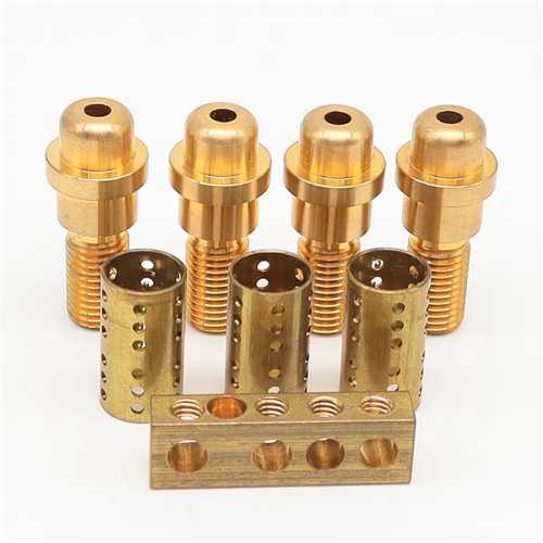
The basic dimensions of a cylindrical internal thread are determined by the nominal diameter (i.e., major diameter) and pitch of the thread. The major diameter (D) refers to the maximum diameter of the thread and is the primary identifier of the thread specification. For example, the major diameter of an M10 thread is 10 mm. The minor diameter (D1) is the minimum diameter of the thread and serves as the reference dimension for the bottom hole during threading. The calculation formula is D1 = D – 1.0825P (P is the pitch). It determines the thread’s load-bearing capacity. A minor diameter that is too small will result in insufficient thread strength, while a minor diameter that is too large will affect the connection’s security. The pitch diameter (D2) is the diameter of an imaginary cylinder at which the thread’s thread thickness and interthread width are equal. It is a key parameter for measuring thread accuracy and is calculated as D2 = D – 0.6495P. The accuracy of the pitch diameter directly affects the thread’s fit. The pitch (P) is the axial distance between the corresponding points of two adjacent threads on the mid-diameter line. The standard pitch series is divided according to the size of the nominal diameter. For example, the standard pitch of M10 is 1.5 mm, and the fine pitch is 1.25 mm, 1 mm, etc. Fine threads are suitable for occasions that require tight connections or thin-walled parts.
The tolerances for cylindrical internal threads are determined by the thread’s precision grade and engagement length. National standards categorize thread precision into precision (Grade 4), medium (Grade 5), and rough (Grade 6). Different precision grades correspond to different tolerance zones. The tolerance zone consists of the tolerance grade and basic deviation. The basic deviation codes for internal threads are G and H. G indicates a positive deviation (i.e., the pitch diameter is greater than the basic dimension), while H indicates zero deviation. For example, an internal thread M10-5G represents an internal thread with a nominal diameter of 10 mm, medium precision, and a basic deviation of G. The engagement length refers to the effective length of the thread engagement and is categorized as short engagement length (S), medium engagement length (N), and long engagement length (L). The longer the engagement length, the larger the tolerance value to compensate for potential cumulative errors during machining and assembly. The selection of tolerances should be based on the thread’s intended use. For example, threaded connections in precision machinery require a higher precision grade (4H), while general structural connections can use a medium grade (5H or 6H).
The tolerances of internal threads primarily control errors in the mean diameter, minor diameter, and pitch. The mean diameter tolerance is the core of thread tolerances, comprehensively reflecting the effects of pitch error and tooth profile half-angle error on thread fit. Excessive mean diameter tolerance can result in threads that cannot be screwed in smoothly or fit too loosely or too tightly. The minor diameter tolerance ensures that the bottom hole size of the thread is within a reasonable range, preventing tap breakage during tapping due to an undersized bottom hole, or reduced thread strength due to an oversized bottom hole. The pitch tolerance controls the axial distance error between adjacent threads. Excessive pitch error can cause interference during thread engagement, increasing screw-in resistance or even preventing screw engagement. In actual machining, the tolerance of internal threads is guaranteed by controlling the precision of the tap. The precision grade of the tap should match that of the internal thread. For example, an H2 tap should be used to machine a 5H-grade internal thread.
Testing the dimensions and tolerances of cylindrical internal threads is crucial for ensuring thread quality. Pitch diameters are commonly inspected using a thread micrometer or the three-pin measurement method. A thread micrometer measures the pitch diameters of threads of varying specifications with an accuracy of up to 0.01 mm by replacing different probes. The three-pin measurement method is a high-precision measurement method that places three gauge pins of equal diameter into the thread groove, measures the distance between them with a micrometer, and then calculates the pitch diameter using a formula. This method is suitable for inspecting high-precision threads. Minor diameters can be inspected using a plug gauge or internal micrometer. The through end of the plug gauge should fit smoothly into the thread, while the stop end should not. This ensures the minor diameter is within tolerance. Thread pitch can be inspected using a pitch gauge or a tool microscope. A pitch gauge visually determines pitch compliance by measuring its fit to the thread profile, while a tool microscope can accurately measure the actual pitch value. Strict dimensional and tolerance control and inspection ensure that cylindrical internal threads meet design and application requirements and achieve reliable mechanical connections.