Diameter of round rod before threading
Determining the diameter of the round rod before threading is a key step in ensuring thread quality, directly affecting the thread’s fit and connection strength. Threading is the process of machining external threads on a round rod using a die. Because the die causes plastic deformation of the round rod material during the cutting process, the major diameter of the thread increases slightly. Therefore, the round rod diameter must be smaller than the nominal diameter of the thread. If the round rod diameter is too large, the die will be overloaded or even chipped. If the diameter is too small, the thread profile height will be insufficient, reducing the connection strength. Test data from a standard parts factory shows that for every 0.1mm deviation of the round rod diameter from the optimal value, the thread qualification rate will decrease by 10%-15%. Therefore, it is crucial to properly determine the round rod diameter.
Calculating the rod diameter before threading requires consideration of the material’s plasticity and thread accuracy. For plastic materials (such as mild steel and copper alloys), due to the significant plastic deformation during threading, the rod diameter should be 0.13-0.2mm smaller than the nominal thread diameter. For brittle materials (such as gray cast iron and hard steel), due to the smaller plastic deformation, the rod diameter can be 0.05-0.1mm smaller. The specific calculation formula is: Rod diameter = nominal thread diameter – (0.13-0.2)P (P is the thread pitch). For example, for an M10×1.5 thread, the rod diameter for mild steel should be 10-0.17×1.5, which is approximately 9.75mm, while the rod diameter for gray cast iron should be 10-0.08×1.5, which is approximately 9.88mm. In actual production, the recommended rod diameter range can be referenced in national standards, or determined through trial cutting. This involves machining a small section of thread, inspecting it with a thread ring gauge, and adjusting the rod diameter based on the tightness. When a machinery factory was processing Q235 steel M12 threads, it determined through trial cutting that the diameter of the round rod was 11.78mm, so that the go/no-go fit of the thread ring gauge was just right.
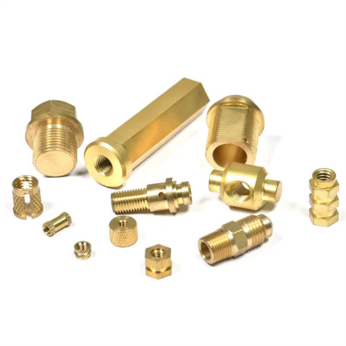
Different thread types have different requirements for rod diameter before threading. Standard coarse threads (such as M8 and M10) have a larger pitch, resulting in greater material deformation, so the rod diameter should be smaller. Fine threads (such as M10×1) have a smaller pitch and less deformation, so the rod diameter can be increased appropriately. The rod diameter of pipe threads (such as G1/2) must match the outer diameter of the pipe, and the wall thickness at the pipe ends must be uniform. Before threading, the pipe’s ovality must be checked. If the error exceeds 0.1mm, straightening should be performed. Trapezoidal and rectangular threads have a higher profile, so the rod diameter must be determined to ensure the thread profile height. It is typically 0.2-0.3mm smaller than the nominal diameter. For example, the rod diameter for a Tr20×4 thread should be 19.7-19.8mm. When machining trapezoidal thread lead screws, a machine tool manufacturer precisely controls the rod diameter to keep the pitch diameter error within 0.02mm, ensuring transmission accuracy.
The processing quality of the round rod before threading has an important impact on the quality of the thread. The end face of the round rod needs to be chamfered with a chamfer angle of 45°-60°, and the chamfer length should be greater than the thread profile height to allow the die to cut in smoothly. The cylindricity error of the round rod should be controlled within 0.03mm/m, and the surface roughness should not exceed Ra3.2μm. If there are scratches, pits and other defects on the surface of the round rod, burrs or tears will appear on the thread surface. For slender round rods with an aspect ratio greater than 10, they need to be straightened before threading to avoid bending and deformation during processing, which will affect the straightness of the thread. When processing bolt round rods, a certain auto repair shop strictly controls the cylindricity and surface quality of the round rods, which increases the qualified rate of bolts after threading from 85% to 98%.
Appropriate tools and methods should be used to measure and control the diameter of the round rod before threading. In workshop production, vernier calipers or micrometers are often used to measure the diameter of the round rod. When high precision is required, an outside micrometer should be used. When measuring, 3-4 points should be measured at different positions on the round rod, and the average value should be taken as the actual diameter. During batch production, special gauges can be used for inspection. The go gauge should be able to pass through the round rod, and the stop gauge should not pass through, to ensure that the diameter of the round rod is within the specified range. A certain standard parts automated production line is equipped with an online diameter detection device that can measure the diameter of the round rod in real time and adjust the cutting parameters of the previous process through the feedback system to control the fluctuation of the round rod diameter within 0.05mm, and the one-time pass rate of threading is stable at more than 99%. With the development of processing technology, the determination of the diameter of the round rod before threading has formed a complete set of process specifications. By combining material properties, thread type and processing equipment, the diameter of the round rod can be accurately controlled, laying a solid foundation for the processing of high-quality threads.