Thread turning is a commonly used thread processing method in machining. Through the coordinated movement of the lathe spindle and tool, threads that meet precision requirements are formed on the workpiece surface. The basic principle is to clamp the workpiece on the lathe spindle and rotate it. The tool is fed at a constant speed along the workpiece’s axis, and the blade cuts a spiral groove on the workpiece surface. Depending on the type of thread and the precision required, thread turning methods can be divided into low-speed turning and high-speed turning. Low-speed turning is suitable for triangular threads and trapezoidal threads with high precision requirements. High-speed turning typically uses high-speed steel tools at cutting speeds of 5-15 m/min. Through multiple passes, the thread is gradually formed, effectively ensuring the thread profile accuracy and surface quality. High-speed turning, which often uses carbide tools, can reach cutting speeds of 30-100 m/min. It is suitable for general thread processing in large-scale production. Leveraging the rigidity of the lathe and the wear resistance of the tool, thread cutting can be completed in a shorter time. A general machinery factory used high-speed turning to process M20 ordinary threads, reducing the single-piece processing time from 2 minutes using low-speed turning to 40 seconds, significantly improving production efficiency.
Tool selection for thread turning requires a comprehensive consideration of thread type, workpiece material, and machining accuracy. The tool tip angle of a triangular thread turning tool must be consistent with the thread profile angle. The tool tip angle is 60° for standard metric threads and 55° for imperial threads. The design of the tool rake and clearance angles must balance cutting sharpness and edge strength. For trapezoidal and rectangular threads, the tool’s cutting edge width and angle must strictly match the thread profile. Typically, a right-angle turning tool with a 90° lead angle is used to reduce the impact of radial cutting forces on the workpiece. When machining high-strength alloy materials, coated carbide or ceramic tools should be selected. Their higher hardness and wear resistance can handle machining at high cutting temperatures. A heavy machinery plant used TiAlN-coated carbide tools to process 42CrMo steel bolt threads. The tool life increased fivefold compared to high-speed steel tools, and the thread surface roughness reached Ra1.6μm.

The process parameters for thread turning directly impact machining quality and efficiency. The cutting speed should be selected based on both the tool and workpiece materials. High-speed steel tools typically maintain a cutting speed of 8-15 m/min when machining steel, while carbide tools can reach 20-50 m/min. When machining non-ferrous metals such as copper and aluminum, the cutting speed can be further increased to 50-100 m/min. The feed rate is related to the thread pitch and must be set strictly according to the “feed = pitch” principle to ensure accurate thread lead. The back-cut should be set in a decreasing manner, with the first pass set at 0.3-0.5 mm and gradually reduced with each subsequent pass, leaving a final finishing allowance of 0.1-0.2 mm to ensure dimensional accuracy. A precision instrument manufacturer optimized the back-cut distribution when machining trapezoidal threads, achieving a pitch diameter tolerance within ±0.015 mm , meeting the requirements of precision transmission.
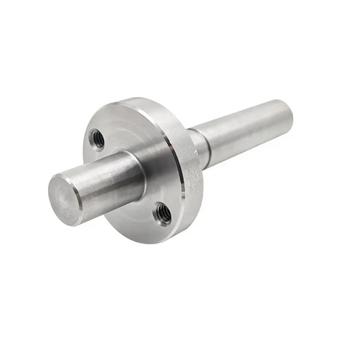
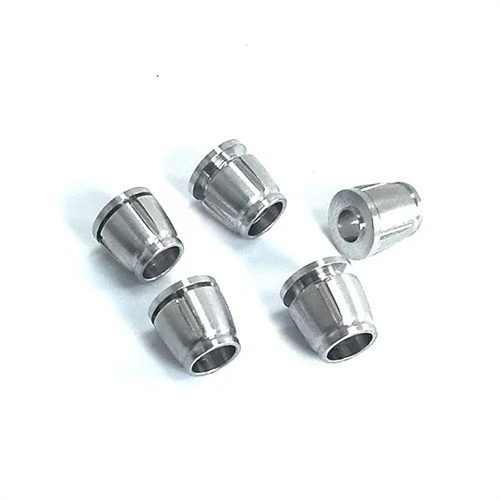
Clamping and tool setting techniques for thread turning are crucial for ensuring machining accuracy. The appropriate clamping method for the workpiece should be selected based on its structural characteristics. Shaft-type workpieces can be clamped using a three-jaw self-centering chuck or a double ejector. Workpieces with a large length-to-diameter ratio should use a steady rest or steady rest to enhance rigidity and prevent bending and deformation during machining. Bushing-type workpieces should be clamped using soft jaws or a mandrel to avoid surface damage or deformation. During tool setting, the tool tip should be aligned with the workpiece axis, and the tool tip angle should be calibrated using a template to ensure symmetry in the thread profile. On CNC lathes, tool setting can be achieved through trial cutting: a small thread section is first turned on the workpiece end face, the actual dimensions are measured, and the tool compensation value is adjusted until the design requirements are met. An automotive parts manufacturer uses a dual ejector and steady rest clamping method for threading slender shafts, combined with trial cutting and tool setting techniques, to keep the cumulative thread error within 0.02 mm/m.
Quality inspection and defect correction during thread turning are crucial steps in ensuring product quality. Common inspection tools include thread micrometers, thread ring gauges, plug gauges, and pitch gauges. Thread micrometers are used to measure the pitch diameter of external threads, while ring gauges and plug gauges are used to verify the conformity of external and internal threads, respectively. Pitch gauges quickly verify the correct pitch. Common defects during thread turning include thread deflection, skewed thread profile, and dimensional deviations. Thread deflection is often caused by an inaccurate transmission ratio between the lathe screw and spindle or loose workpiece clamping, requiring readjustment of the transmission system or tightening of the workpiece. Skewed thread profile may be caused by incorrect tool mounting angles or uneven tool wear, requiring tool recalibration or tool replacement. Dimensional deviations require correction by adjusting the back-cutting depth. A valve manufacturer has established a rigorous thread inspection process, sampling 10% of each batch for comprehensive testing. This ensures a consistently high thread pass rate above 99%, effectively preventing assembly failures caused by thread quality issues.