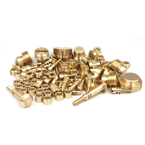
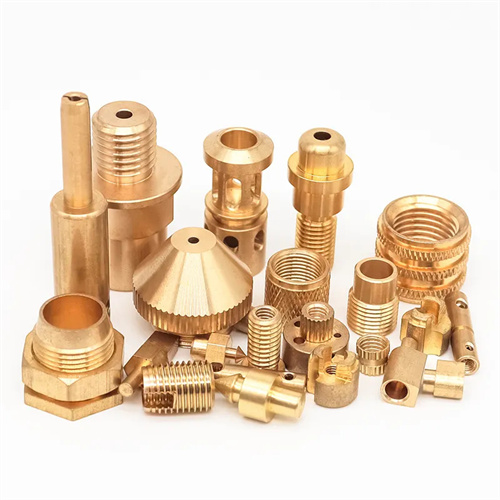
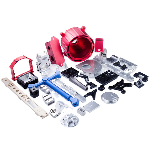
Detection of eccentric workpieces
Eccentric workpieces are parts whose axis deviates from the reference axis. They are widely used in mechanical transmissions, centrifugal mechanisms, and other fields, such as eccentric shafts, eccentric sleeves, and crankshafts. Testing eccentric workpieces is crucial for ensuring assembly accuracy and performance, primarily involving testing parameters such as eccentricity, parallelism of the eccentric axis, and roundness. Eccentricity, the distance between the two axis lines, is the most critical parameter of an eccentric workpiece, and its accuracy directly impacts the kinematic accuracy and balance of the mechanism. For example, excessive eccentricity error in an engine crankshaft can lead to uneven piston motion, vibration, and noise, impacting the engine’s performance and lifespan. Therefore, accurately testing the various parameters of eccentric workpieces is of great practical significance.
There are various methods for measuring eccentricity, and the appropriate method should be selected based on the workpiece’s structural characteristics and precision requirements. For eccentric workpieces with low precision requirements, the line drawing method can be used. A reference axis and an eccentric axis are drawn on both end faces of the workpiece, and the distance between the two lines is measured with a caliper to determine the eccentricity. This method is simple to operate, but offers low accuracy, typically only reaching 0.1-0.2mm. For eccentric workpieces requiring medium precision, a V-shaped iron and a dial indicator can be used. The workpiece’s reference outer diameter is placed on the V-shaped iron, and the workpiece is rotated. The eccentricity is determined by taking half the difference between the maximum and minimum readings on the dial indicator on the eccentric outer diameter. An agricultural machinery manufacturer uses a combination of V-shaped iron and a dial indicator to measure eccentricity to an accuracy of 0.01mm, meeting the requirements of general mechanical transmissions.
The eccentricity detection of high-precision eccentric workpieces requires more sophisticated instruments and methods. A tool microscope is a commonly used device for detecting high-precision eccentricity. The workpiece is mounted on a pin holder, the microscope is adjusted so that the crosshairs are aligned with the reference axis, and the workbench is moved so that the crosshairs are aligned with the eccentric axis. The distance the workbench moves is the eccentricity, and the detection accuracy can reach 0.001-0.005mm. For large eccentric workpieces, a laser interferometer can be used for detection. The high collimation of the laser can be used to measure the distance between the two axes. This not only has high accuracy (up to 0.0001mm), but also enables non-contact measurement, avoiding damage to the workpiece surface. When an aircraft engine factory detects the eccentricity of a large crankshaft, it uses a laser interferometer to ensure that the eccentricity error is controlled within 0.005mm, meeting the balance requirements of the engine at high speed.
It is equally important to detect other parameters of eccentric workpieces. The parallelism error between the eccentric axis and the reference axis will cause additional torque to be generated during the rotation of the workpiece, affecting the stability of the mechanism. It can be detected using a flat plate and a dial indicator. The reference outer circle of the workpiece is placed on the flat plate, and the axial runout of the eccentric outer circle is measured with a dial indicator. The runout is the parallelism error. The roundness error of the eccentric outer circle will affect the fitting accuracy of the workpiece. It can be detected using a roundness meter. The sensor records the radial change of the workpiece during one rotation, and the roundness error value is obtained through data processing. For eccentric workpieces with features such as keyways and planes, it is also necessary to detect the position of these features relative to the eccentric axis. A three-dimensional coordinate measuring machine can be used for three-dimensional detection to ensure that the accuracy of each position meets the design requirements. When a precision machinery factory detects eccentric sleeves, it uses a three-dimensional coordinate measuring machine to comprehensively detect parameters such as eccentricity, parallelism, and position, which increases the product qualification rate to more than 99%.
The inspection of eccentric workpieces is trending towards automation and online testing. With the advancement of industrial automation, the inspection of eccentric workpieces has gradually been integrated into the production process, enabling online, real-time testing. On the production line, robots transport workpieces to inspection stations, where automated testing equipment measures parameters such as eccentricity and roundness. This data is then transmitted to the control system. When deviations are detected, machining parameters are adjusted promptly to avoid batch scrapping. The eccentric shaft production line at an automotive parts manufacturer is equipped with a fully automated inspection system, achieving an inspection rate of 300 parts per hour and an accuracy of 0.002mm. This system also enables traceability and analysis of inspection data, providing data support for process optimization. Furthermore, the application of digital inspection technologies, such as comparing inspection data with 3D models, can quickly identify machining defects in workpieces, improving inspection accuracy and efficiency. It is foreseeable that with the continuous advancement of inspection technology, the inspection of eccentric workpieces will become more efficient and accurate, providing strong support for the high-quality development of mechanical products.