Turning of shank spherical surfaces (five methods)
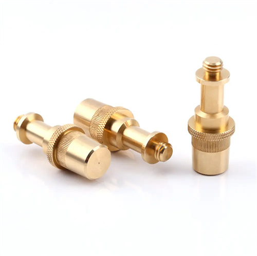
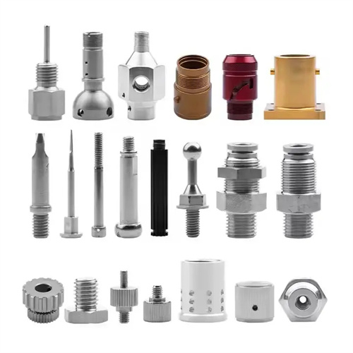
A shank-mounted spherical surface refers to a part with a shank on one end and a spherical surface on the other, such as ball studs and valve balls. These parts are widely used in mechanical transmission and fluid control, and require high roundness, surface roughness, and coaxiality between the shank and the spherical surface. The turning method for shank-mounted spherical surfaces must be selected based on the part’s precision requirements, structural dimensions, and production batch size. Five commonly used methods include manual feed, profiling, CNC interpolation, forming tool turning, and specialized fixtures. Each method has its own applicable scenarios and technical characteristics, and the appropriate selection can achieve efficient and high-precision machining.

The manual feed method is the most basic method for turning shank spherical surfaces. It is suitable for single-piece, small-batch production and applications with low precision requirements (roundness error ≤ 0.1mm). This method involves simultaneously operating the lathe’s longitudinal and transverse feed handles with both hands, causing the tool tip to follow the trajectory of the spherical surface. The contour of the spherical surface should be drawn on the workpiece end face as a reference for feed. Key points for operation are maintaining coordination between the longitudinal and transverse feeds and a uniform feed rate to avoid faceting on the spherical surface due to sudden feed changes. To improve accuracy, a “test cut – measure – adjust” cycle can be employed. After each test cut, the spherical shape is checked with a template and the feed rate is gradually adjusted. The manual feed method requires high operator skill and is suitable for small shank spherical surfaces with a diameter of less than 50mm. The machined surface roughness is generally Ra3.2-Ra1.6μm, making it suitable for general-purpose mechanical parts with low requirements.
The profiling method is a highly efficient method for mass-producing shank-mounted spherical surfaces. A profiling device controls the tool feed trajectory, ensuring consistent spherical shape. The profiling tool is typically a circular plate with the same radius as the workpiece’s spherical surface, fixed to the lathe bed. A roller mounted on the tool holder rolls along the profiling tool’s arc, driving the tool to complete the spherical surface machining. Key to the profiling method is ensuring the accuracy of the profiling tool’s arc (roundness error ≤ 0.01mm) and the proper fit of the roller and profiling tool (contact area ≥ 90%). Adjustment is required to ensure that the center of the profiling tool’s arc coincides with the workpiece’s center of rotation. This method is suitable for shank-mounted spherical surfaces with diameters of 50-200mm. It boasts a 3-5 times improvement in machining efficiency compared to manual feed methods, with roundness errors controlled to within 0.03mm and surface roughness Ra 1.6μm. It is widely used in the mass production of automotive parts.
CNC interpolation is the preferred method for machining high-precision spherical surfaces with handles. Leveraging the circular interpolation function of CNC machine tools, the tool is programmed to follow a circular trajectory along the surface. During machining, the sphere is broken down into several tiny straight or circular segments. The CNC system then controls the tool feed, segment by segment, achieving continuous machining of the sphere. The accuracy of CNC interpolation depends primarily on the interpolation cycle and pulse equivalent. Using a precision CNC lathe (positioning accuracy ≤ 0.001mm), the roundness error of the sphere can be controlled to within 0.005mm, with a surface roughness of Ra0.8-Ra0.4μm. This method is suitable for spherical surfaces of various sizes, especially complex ones (such as incomplete or eccentric spheres). Programming requires accurate calculation of the sphere’s center coordinates and radius to ensure the interpolation trajectory aligns with the theoretical sphere. CNC interpolation offers high flexibility, requiring only program modifications for product changes, making it suitable for high-variety, small- to medium-volume production.
The form-cutting method uses a single feed of a form cutter that conforms to the spherical shape. This method is suitable for mass-produced shank spherical surfaces with small diameters (≤30mm) and medium precision requirements. The cutting edge of the form cutter must be ground to the spherical surface’s curvature radius, with an edge radius tolerance of ≤0.02mm. The rake angle should be 10°-15°, and the relief angle 5°-8° to ensure a sharp edge. A low cutting speed (50-80m/min) and a small feed rate (0.05-0.1mm/r) are used to avoid blade deformation caused by excessive cutting forces. The form-cutting method is highly efficient, 20%-30% higher than the profiling method. However, the cutting edge wears more rapidly, requiring regular sharpening. It is suitable for machining shank spherical surfaces made of plastic materials (such as copper and aluminum alloys), with a typical surface roughness of Ra1.6μm.
The special fixture method is suitable for the processing of large spherical surfaces with handles (diameter > 200mm). The rotational motion of the workpiece is converted into the swinging motion of the tool through the fixture to achieve spherical surface processing. The special fixture usually includes an indexing mechanism, a swinging tool holder and a positioning device. The workpiece is fixed on the main shaft for rotation, and the tool is installed on the swinging tool holder. The swing center of the tool is adjusted according to the radius of the sphere so that the tool’s motion trajectory forms a spherical surface. The advantage of this method is that it can process large spheres, and the fixture structure is simple and low-cost. During processing, the coaxiality of the tool swing center and the workpiece rotation center must be ensured (error ≤ 0.02mm). The special fixture method is suitable for large ball head parts in engineering machinery. The roundness error can be controlled within 0.05mm, and the surface roughness is Ra3.2μm. After processing, it is necessary to further improve the accuracy through grinding.