The influence of chamfer on the theoretical position of the datum plane
Chamfering is a common process in machining mechanical parts. It involves creating a chamfered surface at a certain angle at the corners of a part. Its primary function is to remove burrs, facilitate assembly, and protect operators. However, the presence of a chamfer can have a subtle yet significant impact on the theoretical position of the datum plane. The datum plane serves as a reference for part dimensions and form and position tolerances. The accuracy of its theoretical position is directly related to the part’s assembly precision and functional performance. The size, angle, and position of the chamfer can indirectly affect the theoretical position accuracy of the datum plane by changing its actual contact state, measurement basis, and force distribution. Therefore, this must be fully considered during design and machining.
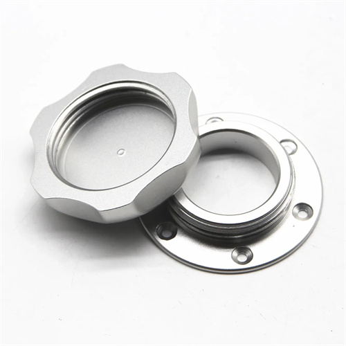
The impact of chamfer dimensions on the theoretical position of the datum plane is primarily reflected on the assembly contact surface. When a part’s datum plane contacts the surface of another part, chamfering the edge of the datum plane reduces the actual contact area, causing the effective support area of the datum plane to shift toward the center, thereby offsetting the theoretical datum position. For example, a datum plane (100mm diameter) with a 1×45° chamfer has an actual contact ring width that is 1mm smaller than that without the chamfer. If there is an error in the concentricity of the contact ring, the theoretical center of the datum plane will deviate by 0.01-0.03mm from its actual center. For high-precision assembly (such as the contact between machine tool guide rails and slides), the chamfer dimensions must be strictly controlled. Generally, the chamfer width should not exceed 0.5mm and the angle should be 45° to minimize the loss of contact area and ensure the stability of the theoretical position of the datum plane.
The chamfer angle affects the theoretical position of the datum plane by changing the stress state of the part. In parts subject to axial loads, the chamfer angle of the datum plane determines how the load is distributed. A 90° chamfer (i.e., a right-angle chamfer) concentrates the load at the edge of the datum plane, causing slight deformation and shifting the theoretical datum position toward the center. A 120° obtuse chamfer, on the other hand, distributes the load more evenly and reduces deformation. For example, when the datum plane of a bearing end cap is chamfered with a 1×120° angle, its flatness error is 30% less than that of a 45° chamfer, and the deviation from the theoretical datum position is controlled within 0.005mm. For parts subject to alternating loads (such as engine connecting rods), the chamfer angle selection must be verified through finite element analysis to ensure that the theoretical position error of the datum plane is minimized under load.
The machining accuracy of chamfers significantly impacts the measurement datum of the datum plane. When inspecting the flatness, parallelism, and other geometric tolerances of a datum plane, the probe of a measuring instrument (such as a dial indicator or flatness measuring instrument) contacts the datum plane. If the chamfer has dimensional errors or angular deviations, the contact point between the probe and the datum plane will deviate from the theoretical position, introducing measurement errors. For example, when the actual chamfer angle is 40° (designed to be 45°), the probe’s contact point 1mm from the edge will be offset 0.087mm toward the center, resulting in a 0.01mm error in the flatness measurement. Therefore, the machining accuracy of the chamfer must match the accuracy grade of the datum plane. When the datum plane is IT5, the angular tolerance of the chamfer should be controlled within ±1°, and the dimensional tolerance within ±0.1mm to ensure the accuracy of the measurement datum.
The chamfer position has a significant impact on the clearance between the datum plane and other parts. In a clearance fit, the chamfer of the datum plane can alter the actual clearance between the mating surfaces. For example, excessive chamfering of the shaft shoulder datum plane can increase the clearance between the shaft and the hole, shifting the shaft’s axial reference position backward. For example, in a φ50H7/h6 fit, a 2×45° shoulder chamfer increases the actual clearance by 0.01-0.02mm compared to no chamfer, and the shaft’s reference position shifts by approximately 0.01mm. For precision fits (such as the spool and sleeve of a hydraulic valve), the chamfer size must be determined through calculation. Generally, a chamfer width of 1-1.5 times the clearance ensures smooth assembly without compromising reference position accuracy. Furthermore, in welded parts, the chamfer position affects the strength distribution of the weld, indirectly altering the deformation of the datum plane under load. Therefore, optimal chamfer placement requires welding process testing.
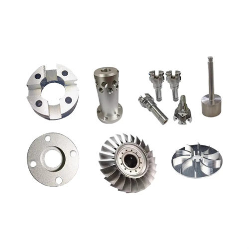
The influence of chamfers on the theoretical position of the datum plane of special structural parts requires special treatment. For thin-walled parts, chamfering may cause local deformation of the datum plane. A symmetrical chamfer design is required to offset the deformation. For example, symmetrical 1×45° chamfers are set on both end faces of a thin-walled flange to reduce the flatness error after processing. For the datum plane of a stepped shaft, continuous chamfers need to be set at each step to avoid datum position steps caused by discontinuous chamfers. The angles of continuous chamfers should be consistent, and the dimensions should be adjusted according to the proportion of the step diameter. Through three-dimensional modeling and simulation analysis, the influence of chamfers on the theoretical position of the datum plane can be evaluated in advance, and the chamfer parameters can be optimized during the design phase to control the theoretical position error of the datum plane within the allowable range, thereby ensuring the assembly accuracy and functional reliability of the parts.