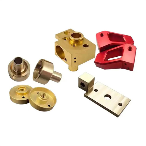
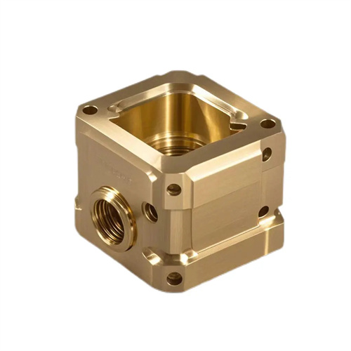
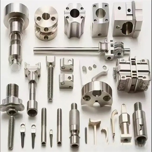
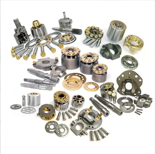
Different surface processing solutions
The profile of a mechanical part refers to the surface morphology that constitutes the part’s geometric features. These include planes, cylinders, cones, spheres, threads, and various complex curved surfaces. Machining solutions for different profiles must be comprehensively formulated based on the part’s material, precision requirements, structural characteristics, and production batch size. A sound process plan not only ensures machining quality but also improves production efficiency and reduces manufacturing costs. Common surface machining techniques include turning, milling, grinding, boring, and planing. Complex profiles require the use of advanced techniques such as CNC machining and specialized machining.
The surface machining process should be selected based on the surface’s accuracy level and surface quality requirements. For surfaces with lower accuracy requirements (IT11-IT13) and a surface roughness of Ra12.5-Ra6.3μm, rough milling or rough planing can be used to achieve the required surface finish in a single pass. This process is suitable for rough surface machining of materials such as cast iron and carbon steel. When accuracy requirements increase to IT8-IT10 and surface roughness of Ra3.2-Ra1.6μm, a “rough milling-fine milling” or “rough planing-fine planing” process is required. For steel parts, tempering treatment can also be added to increase material hardness. For high-precision flat surfaces (IT5-IT7 grades) with a surface roughness of Ra0.8-Ra0.025μm, a “rough milling-fine milling-grinding” process is required. Grinding uses a grinding wheel grit of 80#-120#, a grinding depth of 0.01-0.03mm, and a feed speed of 5-10m/min, ensuring a flatness error of ≤0.01mm/m. For flat surfaces of large flat plates, a scraping process can also be used. Manual scraping reduces the number of contact points to 12-16 per 25×25mm², meeting the assembly requirements for precision machine tool guideways.
Machining of rotating surfaces (cylindrical and conical surfaces) primarily relies on turning and grinding, with process plans tailored to the required precision levels. Rough turning removes most of the stock, achieving IT12-IT13 precision and a Ra12.5μm roughness. Semi-finish turning improves precision to IT10-IT11 with a Ra6.3-Ra3.2μm roughness. Finish turning achieves IT7-IT8 precision with a Ra1.6-Ra0.8μm roughness, making it suitable for the final machining of non-ferrous metal parts. For high-precision rotating surfaces (IT5-IT6) on ferrous metal parts, grinding is added after finish turning. External cylindrical grinding employs a “rough grinding-finish grinding-superfinishing” process, while internal grinding requires careful consideration of the matching of the grinding wheel diameter to the inner hole diameter (0.5-0.8 times the inner hole diameter). For conical surface machining, small tapers (≤1:30) can be achieved by lathe tailstock offset, while large tapers require a dedicated angle tool holder or G function programming of the CNC lathe to ensure that the taper error is ≤0.01mm/m.
Complex curved surfaces require CNC machining technology, with the appropriate process selected based on the surface type. For regular curved surfaces (such as spheres and paraboloids), the circular interpolation function of a CNC lathe or milling machine can be used, using a ball-end milling cutter or a circular turning tool. The cutting spacing is set according to the surface roughness requirement (≤0.1mm for Ra1.6μm). Free-form surfaces (such as the surface of automotive panel molds) require a three-axis or five-axis CNC milling machine. A ball-end milling cutter is used for layered cutting, with a depth of 0.1-0.3mm per layer and a feed rate of 500-1000mm/min. Tool paths are generated using CAM software to ensure smooth surface transitions. For hardened surfaces with a hardness exceeding HRC50, sinker EDM or wire EDM is used, utilizing electro-erosion to remove material and minimize tool wear. The machined surfaces are inspected using a coordinate measuring machine, with the measured data compared to the CAD model. Any discrepancy exceeding 0.02mm requires remachining.
The thread surface machining process should be selected based on the thread type, precision grade, and material properties. Common triangular threads can be roughed using either turning or rolling. Turning is suitable for single-piece, small-batch production, while rolling is suitable for large-scale production of external threads (diameter ≤ 20mm), increasing thread strength by 20%-30%. Precision threads (such as machine tool lead screws) require a “rough turning – tempering – semi-finishing turning – rough grinding – fine grinding” process, using single- or multi-thread grinding wheels. Thread accuracy can reach 6h, with a pitch error of ≤ 0.01mm/100mm. Specialized thread turning tools or milling cutters can be used for special-shaped threads (such as trapezoidal and serrated threads). CNC lathes are automatically programmed using the G76 command to ensure accurate thread profiles. Internal thread machining methods vary depending on the diameter: small diameter internal threads (≤M10) are processed using tapping, large diameter internal threads (≥M12) can be processed using boring or milling, and hardened internal threads require EDM. After machining, threads must be inspected using a thread gauge or the three-needle probing method to ensure they meet design requirements.