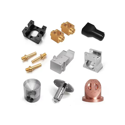
Lathe oil tank
Lathe oil grooves are grooves machined into the surfaces of rotating parts such as shafts and sleeves to store lubricating oil. Their purpose is to reduce friction and wear during relative motion, thereby improving mechanical transmission efficiency and service life. Oil grooves are typically rectangular, semicircular, or trapezoidal in shape, with dimensions determined by the part’s operating environment and lubrication requirements. Common widths range from 2 to 10 mm, and depths from 1 to 5 mm. When machining an oil groove on a lathe, the appropriate machining method and tooling must be selected based on the part’s material, structural characteristics, and the required oil groove accuracy to ensure dimensional accuracy and surface quality.
There are two main methods for machining oil grooves on lathes: direct turning with a profile cutter and machining with a dedicated oil groove tool. Direct turning with a profile cutter is suitable for simple oil grooves and small to medium-sized batch production. The principle is to install the profile cutter on the tool holder and adjust the tool position so that the cutting edge shape of the tool matches the cross-sectional shape of the oil groove. While the workpiece rotates, the tool is fed axially to complete the oil groove machining. For example, when machining a semicircular oil groove, a round-head profile cutter with the same radius as the oil groove is selected, and the tool head width is equal to the oil groove width. A single feed can produce an oil groove that meets the requirements. This method is simple to operate, but for deep or wide oil grooves, multiple feeds are required to avoid tool damage or workpiece deformation due to excessive cutting forces.
Special oil groove drawing tools are suitable for mass production and the processing of oil grooves of complex shapes. Its structure includes a tool bar, a blade and a feed mechanism. The blade can be quickly replaced according to the shape of the oil groove. The tool is installed on the lathe slide box, and the feed movement of the lathe drives the tool to move axially. At the same time, the blade cuts into the surface of the workpiece under the action of radial force to form an oil groove. The feed rate of the special tool can be precisely controlled by adjusting the feed mechanism, generally taking 0.1-0.3mm/r, which can ensure the consistency of the oil groove depth. For situations where oil grooves need to be processed at both ends or in the middle of the part, a limit device can be installed on the tool to accurately control the starting and ending positions of the oil groove with an error of no more than ±0.1mm. In addition, special tools are usually equipped with a cooling system that can take away cutting heat and chips in time to avoid burns or scratches on the surface of the oil groove.
Different materials require different cutting parameters and tool materials when machining oil grooves. For brittle materials like cast iron, where chips are easily dislodged in fragments, YG6 carbide tools can be used at a cutting speed of 80-120 m/min and a feed rate of 0.2-0.3 mm/r to improve machining efficiency. For plastic materials like 45 steel, where chips tend to wrap around the tool, YT15 carbide tools should be used at a cutting speed of 100-150 m/min and a feed rate of 0.15-0.25 mm/r. Emulsion cooling should be used to prevent built-up edge. For difficult-to-machine materials like stainless steel, YW2 carbide tools should be used, with a reduced cutting speed of 60-80 m/min and a feed rate of 0.1-0.2 mm/r to minimize cutting forces and reduce tool wear. After machining, the oil groove should be checked for size and shape using a vernier caliper and a template to ensure it meets design requirements.
Quality control for oil groove machining requires attention to the following aspects: First, the positioning accuracy of the oil groove. By installing a locating sleeve on the lathe spindle or using a dial indicator to calibrate the workpiece, ensure that the parallelism error between the oil groove and the part axis does not exceed 0.1 mm/m. Second, the surface roughness of the oil groove . By selecting appropriate tool geometry (rake angle 10°-15°, clearance angle 6°-8°) and cutting parameters, the surface roughness of the oil groove should be maintained below Ra3.2μm. Third, to avoid workpiece deformation during machining, for thin-walled sleeve-like parts, a soft-jaw chuck or axial clamping should be used, with the clamping force controlled within an appropriate range. Furthermore, the machining of cross-shaped or annular oil grooves can be achieved by adjusting the lathe’s feed mode: cross-shaped oil grooves utilize a combination of longitudinal and transverse feeds, while annular oil grooves are machined by disabling the longitudinal feed and retaining only the transverse feed. By strictly controlling each step of the machining process, the quality of the oil groove can be guaranteed, providing reliable assurance for the proper lubrication of mechanical parts.